Determination of Young's modulus
Using the Cantilever Method
Determine the Young's modulus of a rod by measuring the deflection of a cantilever under known loads.
Objective
Section 01Aim
Determination of Young's modulus of the material of a rod by the cantilever method.
Learning Objectives
After completing this experiment, students will be able to:
- Understand the principle of bending of a cantilever.
- Measure the length and cross-sectional dimensions of the rod.
- Measure the deflection produced by known loads.
- Verify that deflection is proportional to the applied load within the elastic limit.
- Determine Young's modulus from the load-deflection relation.
- Plot and interpret the load versus deflection graph.
- Identify sources of experimental error and estimate the reliability of the result.
After completing this virtual experiment, learners will be able to:
- Explore cantilever bending under controlled loads.
- Vary the load and observe the corresponding free-end deflection.
- Record and analyze virtual observations using the observation table.
- Determine Young's modulus from the slope of the load-deflection graph.
- Investigate the effect of dimensions and measurement uncertainty on the result.
- Compare the virtual result with the expected elastic behavior.
Theory
Section 02Determination of Young's Modulus Using the Cantilever Method
A cantilever is a beam that is fixed rigidly at one end and free at the other. In this experiment, a load P is applied at the free end of the beam, causing a vertical deflection δ.
For a cantilever of length L, Young's modulus Y is related to the deflection by
δ = PL3 / 3YI
where I is the geometrical moment of inertia of the cross-section of the beam.
Rectangular Cross-section
For a rectangular cross-section of width a and thickness b,
I = ab3 / 12
Therefore, the Young's modulus is
Y = PL3 / 3Iδ
Substituting the value of I gives
Y = 4PL3 / ab3δ
Derivation
Consider a section of the cantilever at a distance x from the fixed end. The bending moment at this section is
M = P(L − x)
According to the bending equation,
YI d2y/dx2 = P(L − x)
Integrating twice and applying the boundary conditions at the fixed end, y = 0 and dy/dx = 0 at x = 0, we obtain
y = Px2(3L − x) / 6YI
Maximum Deflection and Measurement
At the free end, x = L, the deflection is maximum and is equal to δ. Hence,
δ = PL3 / 3YI
Thus, by measuring the load P, length L, dimensions of the beam, and deflection δ, the Young's modulus of the material can be determined.
Apparatus Required
Section 03Apparatus
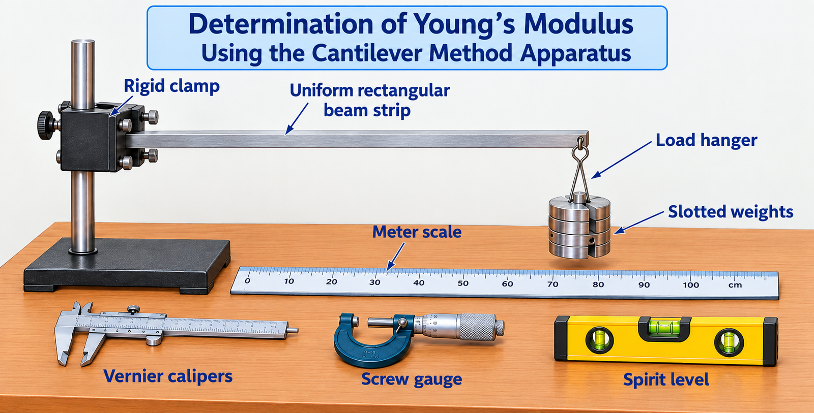
- Uniform rod and rigid clamp
- Load hanger and slotted weights
- Meter scale
- Vernier calipers
- Screw gauge
- Dial gauge or microscope for measuring deflection
- Spirit level and graph paper
Procedure
Section 04Procedure (Real Experiment)
- Measure the length and width of the beam using a Vernier caliper.
- Measure the thickness of the beam using a screw gauge.
- Fix one end of the beam firmly in a clamp so that the other end remains free.
- Use a spirit level to ensure that the beam is horizontal.
- Set up the measuring scale vertically at the free end to measure the deflection.
- Record the initial reading of the measuring device with the beam unloaded.
- Place the hanger at the free end of the cantilever.
- Add weights to the hanger in increments, for example 50 g, 100 g, 150 g, and so on.
- For each load, record the new reading on the measuring device.
- Calculate the deflection for each load as the difference between the loaded and unloaded readings.
- Repeat the loading measurements for at least five different weights.
- After completing the increasing-load observations, repeat the process with decreasing weights to check for hysteresis.
- Calculate Young's modulus using the cantilever formula for each set of readings and determine the average value.
Procedure (Virtual Experiment)
- Open the cantilever simulation in Full Screen mode.
- Choose the beam-strip material using the material drop-down menu.
- Set the length, width, and thickness of the beam strip using the available sliders.
- Note the moment of inertia for the selected beam dimensions as shown in the simulation.
- Select a load using the simulation slider labelled Load (m).
- Observe the free-end deflection and record the mass and deflection readings.
- Repeat the measurement for several different loads.
- Record all readings in the observation table in the Observations section.
- Click Plot Graph to open the Result and Analysis section and plot the submitted observation data.
- Note the slope from the graph, then click Next to open the freehand calculation area.
- Calculate Young's modulus using the displayed formula.
- Enter and submit the result in the input box.
- Click Export PDF to download the completed experiment report.
Simulation
SimulationObservation Table
Section 06Young's Modulus / Cantilever Observation Table
Result and Analysis
Section 07Result summary
Use the measured loads and deflections to determine the slope and Young's modulus of the rod.
Calculation on freehandTool
Y = (1/3) × (gL3)/(Slope × I); I = (w × h3)/12
Assessment
10 MCQsYoung's Modulus by Cantilever Method
Answer all ten moderate-level questions and submit the quiz to view your score.